Did you ever wonder how does this fancy graphics of flow, air, stress, etc. render in the SOLIDWORKS Simulation add-in? That’s not a typical geometry you see in SOLIDWORKS, it doesn’t have feature in feature manager tree. What about the geometry when you import STL file? How come you can see it but cannot edit (unless STL imported as body)? And why it is so fast, rotating, zooming, panning doesn’t affect performance even if you render millions of triangles?
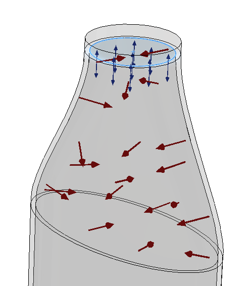
There are also various 3rd party add-ins which render light rays, sound waves, red line markups etc. which obviously do not have access to internal SOLIDWORKS functions and can only utilize SOLIDWORKS API. So, how to render this graphics in SOLIDWORKS API?
The answer is OpenGL. It is a high performance cross-platform library to render the 3D graphics which is used in gaming, virtual reality and CAD applications. And SOLIDWORKS enables developers to hook into the Buffer Swap Notification and render custom objects. Furthermore it calculates all of the rotation and scale matrix for you and with just few lines of code your augmented SOLIDWORKS model is ready.
The code below creates a triangle with coordinates in meters {0,0,0}-{0,1,0}-{1,0.5,0}.
private void OnBufferSwap()
{
    glBegin(GL_TRIANGLES);
    glVertex3d(0, 0, 0);
    glVertex3d(0, 1, 0);
    glVertex3d(1, 0.5, 0);
    glEnd();

    return 0;
}
Follow the Render Tetrahedron And Handle View Display Modes for a code example of rendering tetrahedron geometry.
OpenGL library provides a large variety of methods to work with graphics. It is possible to use different colors, shaders, transparency, draw primitives, text, images etc. Explore the OpenGL Documentation for a detailed guide.
Look at Render Box Grid With Transparency example which demonstrates how to render the grid of cubes with transparency. Cube parameters can be configured by changing the values of constants in the add-in.
This example can be used to demonstrate the limitation of the approach used in previous two examples in relation to performance. Try to change the the number of rendered cube instances to 300000:
private const int INST_COUNT = 300000;
Now, when you try to rotate, pan or zoom the model you will notice huge performance decrease. The reason is all of the coordinates are calculated and rendered in every repaint which could be equal to hundred of times in a simple rotate operation.
So, how to address this issue? The answer is Vertex Buffer Object (VBO). This is a great feature provided by OpenGL and allows to upload the rendering data (such as vertex coordinates, colors, normals) to the video card and render it directly by the video card.
Follow the Import XAML File And Render Using VBO for an example project which using this technique to render the geometry from the XAML format.
Notes
- Draw OpenGL objects within the ModelView::BufferSwap notification provided by SOLIDWORKS API.
- Prefer VBO over the simple rendering techniques to draw OpenGL graphics to gain maximum performance
- Use IModelDocExtension::SetVisibleBox SOLIDWORKS API to set the boundary of the OpenGL geometry if it needed to be respected in the Zoom To Fit operation.
- Explore the OpenGL Documentation for best practices, techniques of using the framework to render 3D geometry. The above examples demonstrate the simplified techniques for getting started with rendering graphics in SOLIDWORKS. Use OpenGL documentation for more sophisticated examples and guidelines for using OpenGL API.